Assembly
To protect the boards during transport, they ship only partially assembled. Before you can use them, you need to solder the stacking headers on them.
Warning
Soldering the headers is a necessary step, and can’t be skipped. Just inserting the headers without soldering will not provide a robust electrical connection that is required for this shield to work properly.
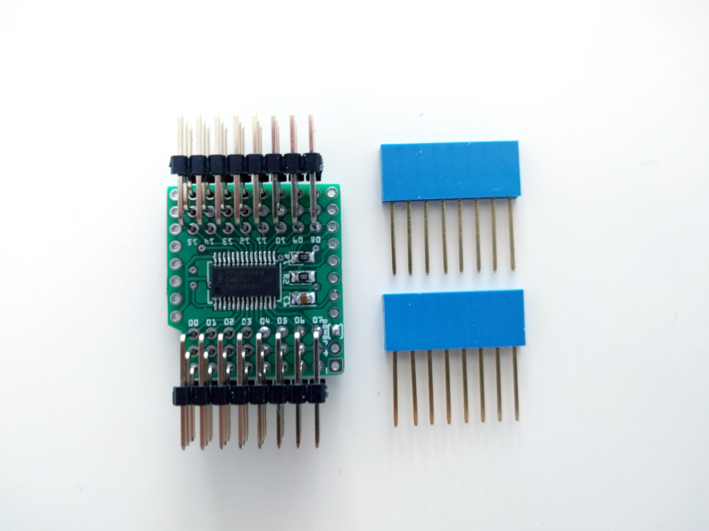
Stacking Headers
You should have received a pair of 8-pin stacking headers with your board. They let you put this shield either on top or on the bottom of the D1 Mini, and stack more shields on top (or bottom) of that.
Note
If you want to, you can instead use normal male or female headers, or even connect the shield to the microcontroller board by soldering the wires or male headers to both boards directly. In either case, the procedure is similar.
Start by putting the headers on your board, or any other already assembled shield. This will hold them in place straight and make it easier to work.
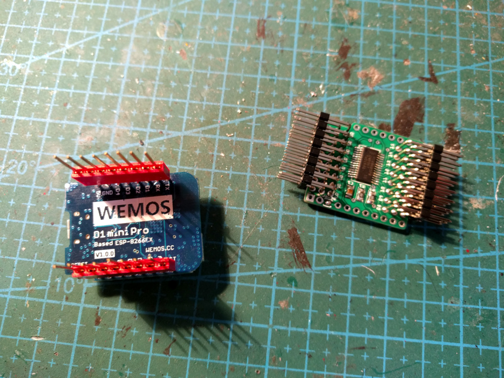
Then place the shield on the headers, making sure that every pin goes into its hole. You might need to use tweezers to help you insert all the pins.
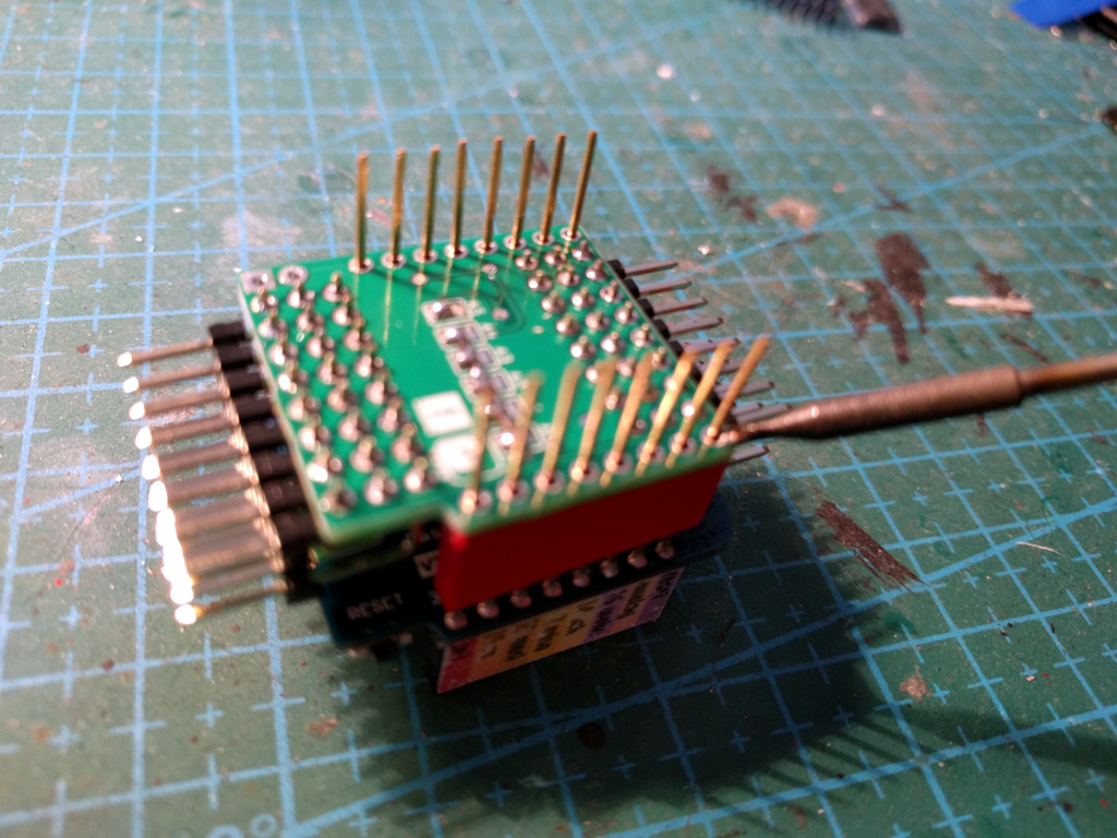
Next, connect your soldering iron, wait for it to get hot, and put it on one of the pins, so that it touches both the pin and the board.
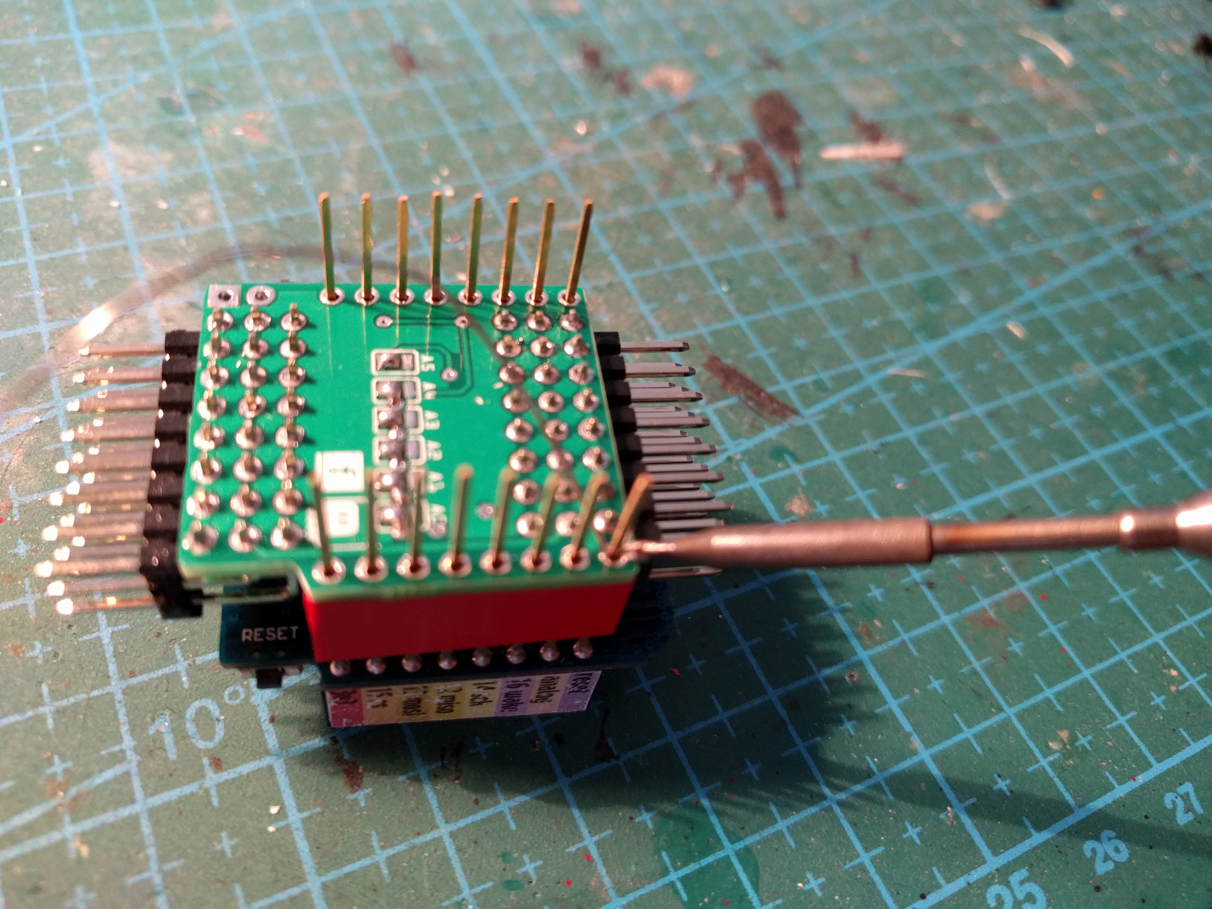
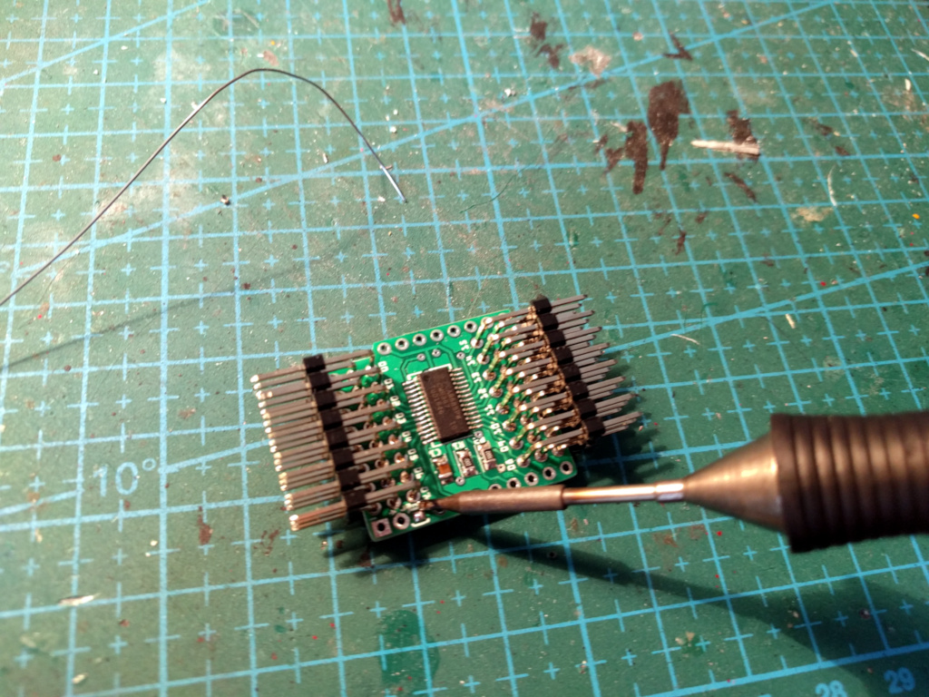
Wait a couple of seconds for the pin to get hot, and then touch the pin and the board with the solder wire. Let the solder flow into the hole around the pin. Then remove the solder wire and the soldering iron, and move to the next pin.
Repeat that for each of the 16 pins. Done.
External Power Source
If you want to power your servos from a different power source than the microcontroller board, you need to remove the drop of solder from the jumper next to the power connector, and solder the connector or wires for the power to the two additional holes. The square hole is minus, the round one is plus.
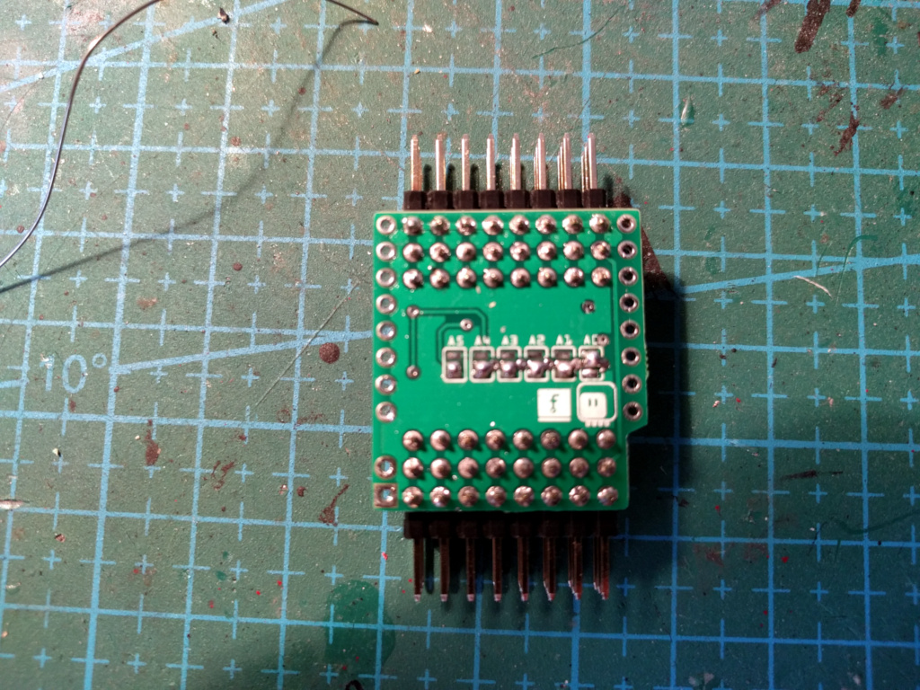
Address Selection Jumpers
On the back of the board, there are six jumpers, labeled A0 to A5, which let you change the default I²C address of the board. By default, they are all set to 0, which sets the address to the value of 0x40. If you plan to stack several of those boards together on the same microcontroller board, you need to change their addresses, so that every one of them has a different one. There are 64 possible combinations.
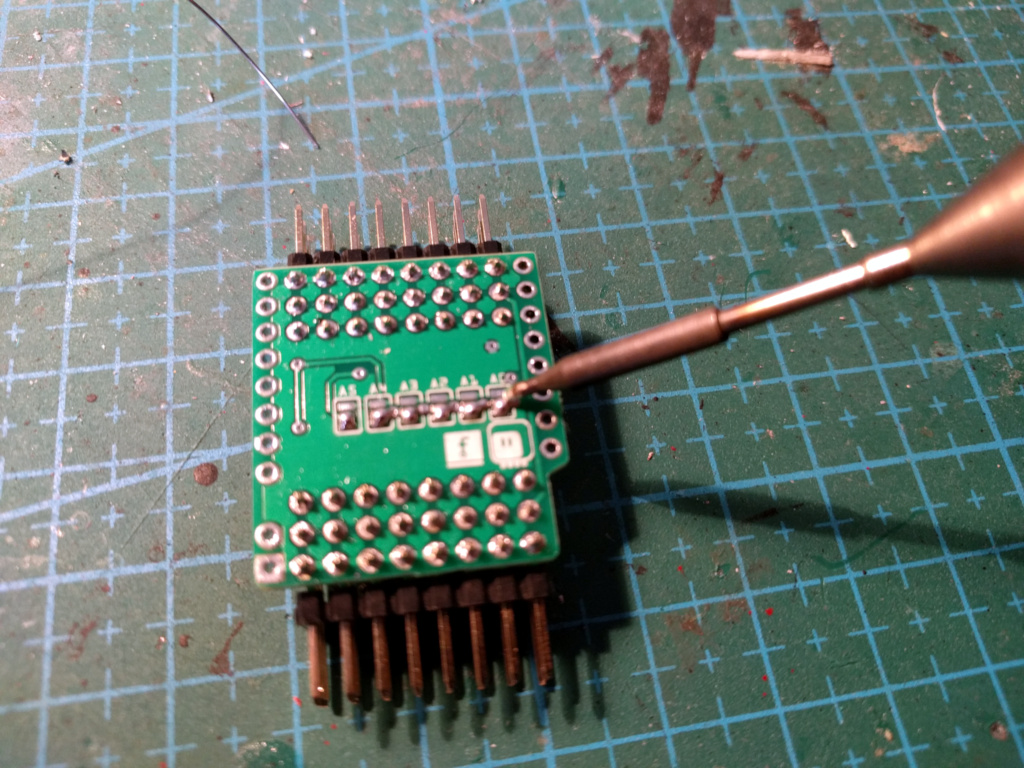
Warning
Be careful to not connect a jumper both to the top and bottom pads, as that will result in an electric short, a lot of smoke and possibly permanently damaged shield, microcontroller board, battery or any other power source used (including your computer, if you powered it from USB).
It is recommended to check the connections with a multimeter before applying power to the device.